The structure of a monitor system consists of the following elements
- Longitudinal rails & cross slides
- Motorized electric lifting column
- Flat screen monitor in different versions according to requirements
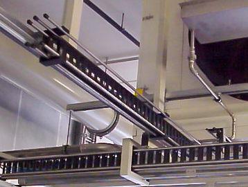
- Energy chain
And is mounted with the following accessories
- Remote controls
- 230 V connection
- Air brake
Front view
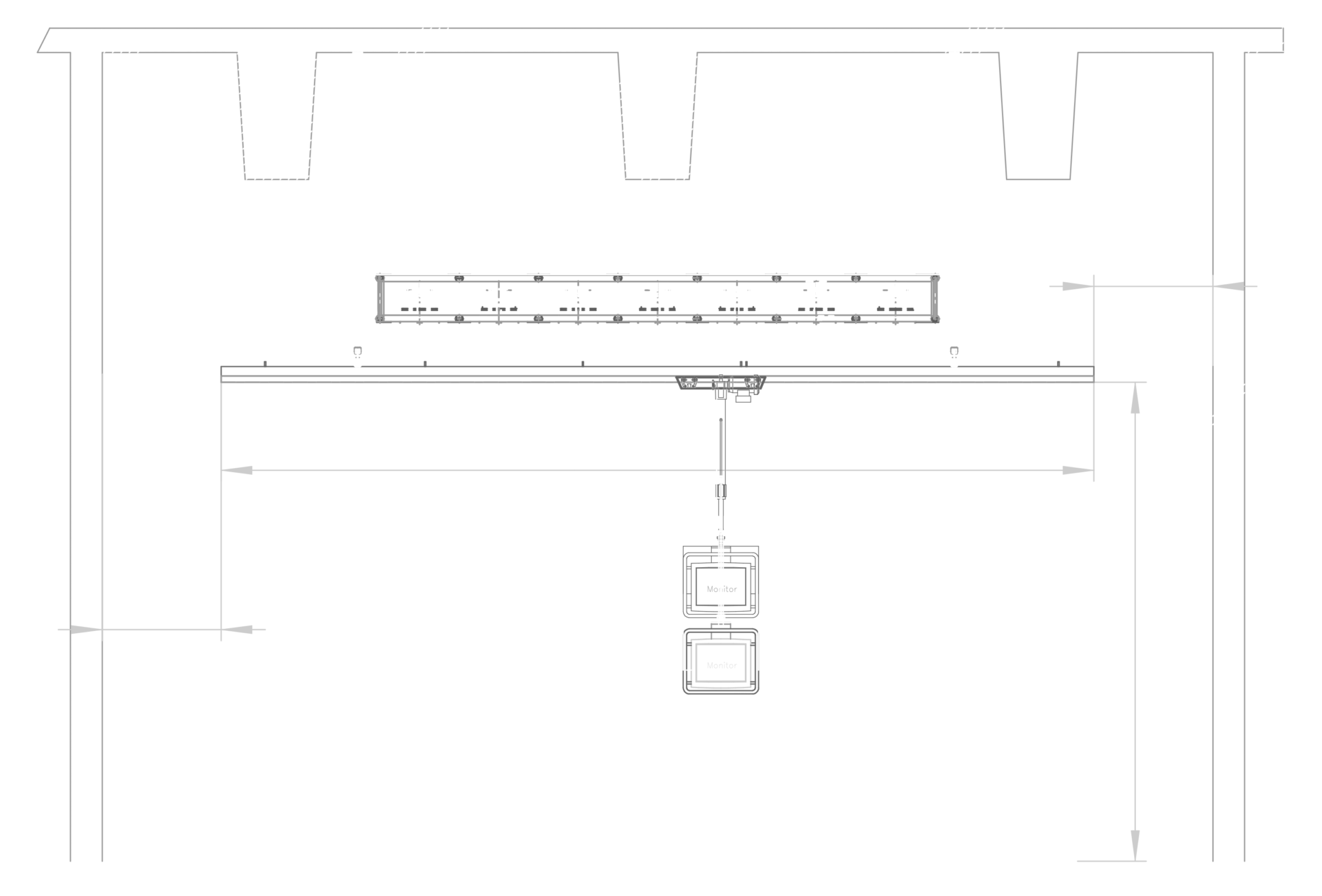
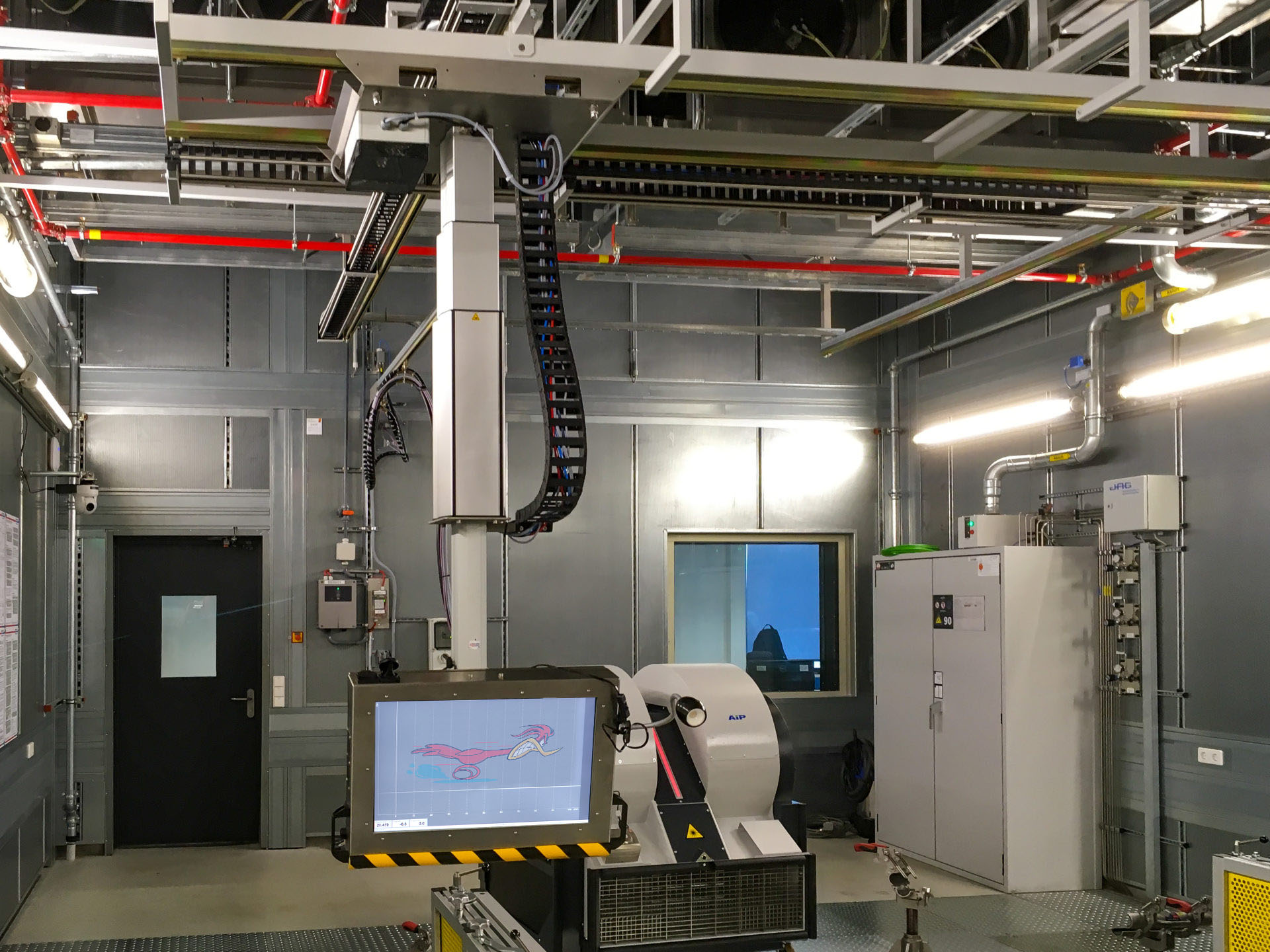
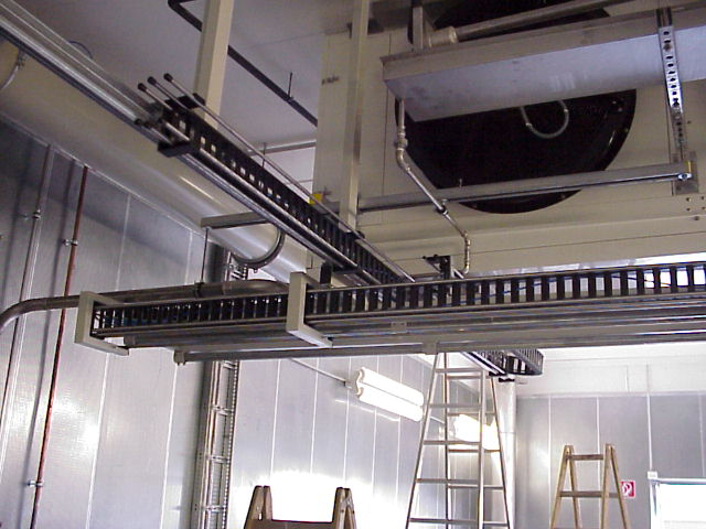
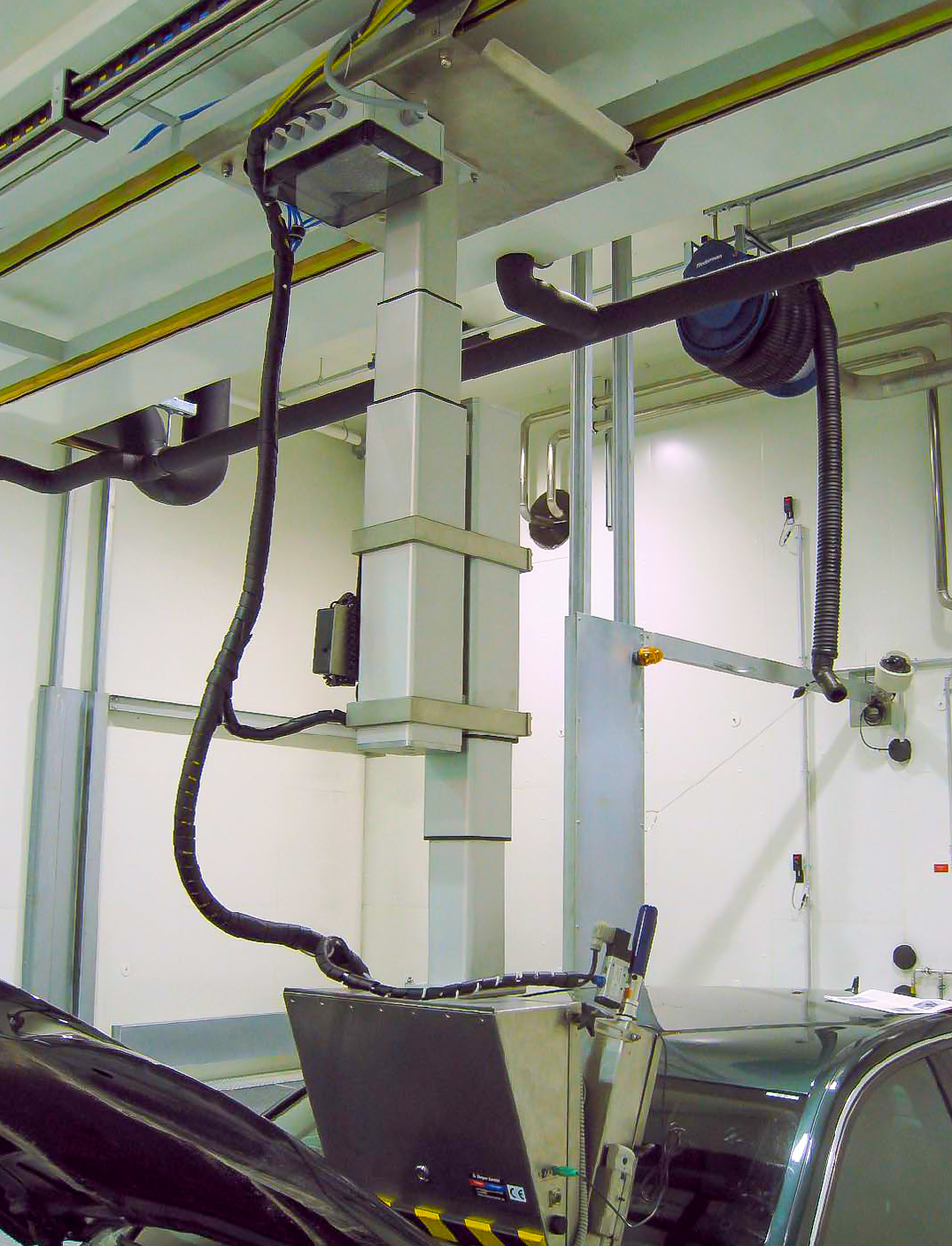
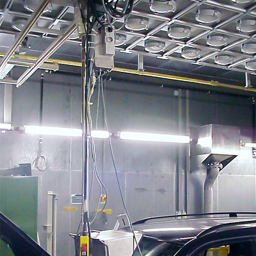
Monitor system setup
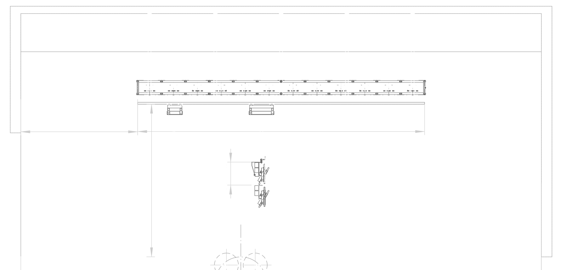
- Ceiling substructure (Variable)
- Longitudinal rails (x-axis, front/rear),
- Longitudinal slide (x-axis, front/rear),
- Monitor cart (y-axis, left/right) with lifting column (z-axis, up/down)
- Monitor
- Sun simulation (optional)
The side and front views show the essential elements of a movable monitor system. The dimensions shown in blue depend entirely on your requirements and the conditions in your test room.
Side view



Carriage & Lifting column
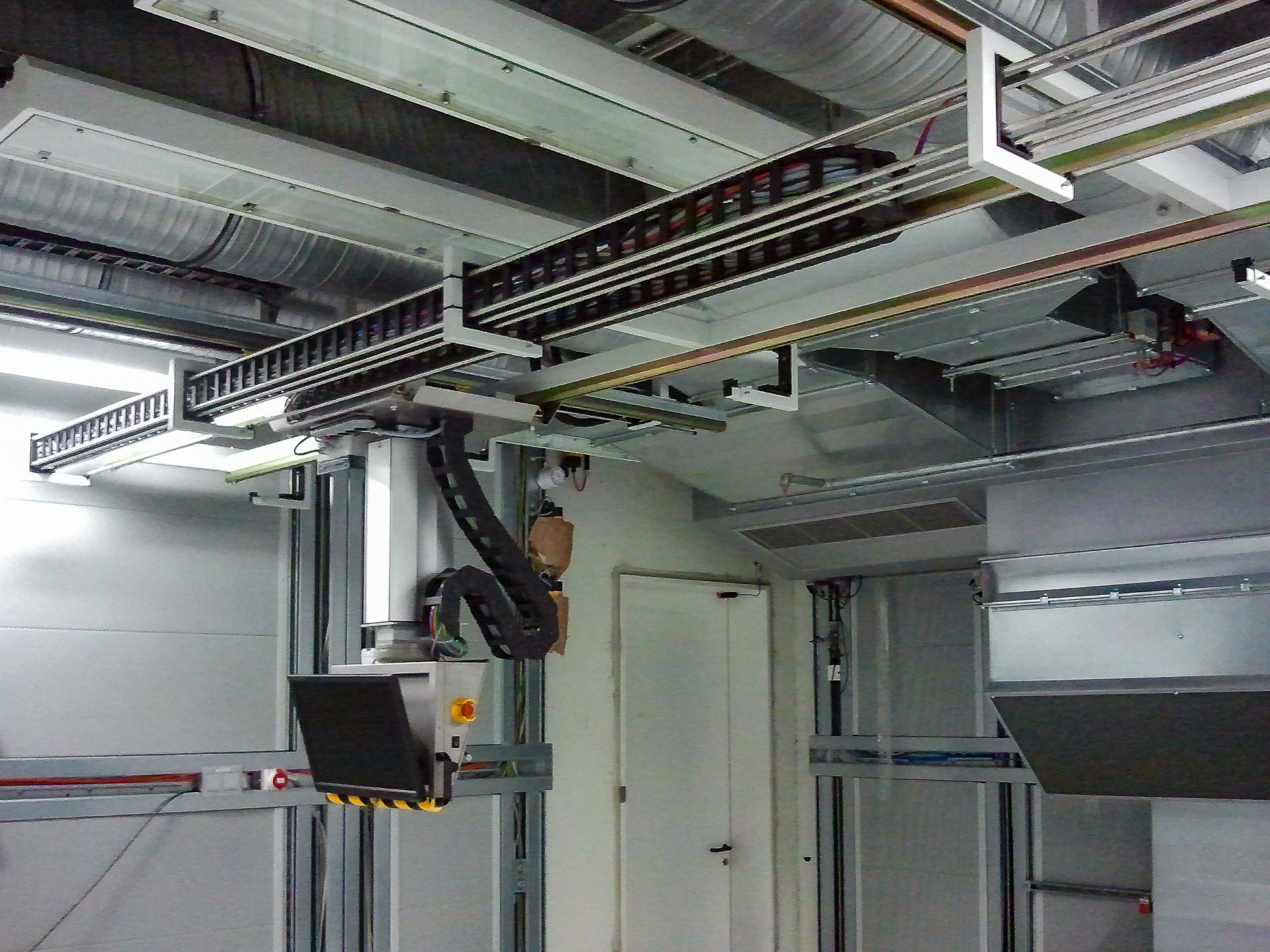
Longitudinal rails, longitudinal slide
The longitudinal rails are mounted vibration-free on the ceiling of the test room. The entire monitor system can be moved along the longitudinal rails in the x-direction. The monitor cart can be moved along the y-axis. The entire system can be locked in any position by means of an air brake.

Lifting column
The lifting column is attached to the monitor cart. It is a motorized telescope with self-locking and end position switch. The motor of the lifting column is thermally protected, the entire lifting column is maintenance-free.
Monitor

Monitor: standard version
The size of the built-in flat screen monitor is entirely up to your preference. Standard size is 24 inch screen diagonal.
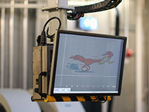
In the standard version (see photo on the left), the monitor is freely accessible. Thus it can be removed quickly and easily and (depending on the cable length) can also be moved into the vehicle.
The monitor is tiltable and thus adaptable to the angle of the windscreen.
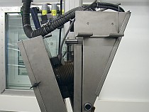
Monitor: climatic chamber version
In addition to the standard version, S. Bleyer GmbH also offers an enclosed climate chamber version of the monitor carrier. Here, the monitor is thermally insulated from the environment and can be heated or cooled.
This allows operation in climatic chambers in a temperature range from -40 °C to +60 °C or under a sun simulation.
Other elements
Energy chain
Remote controls
Holding devices are installed on the side of the monitor support to which various remote controls can be attached or hooked in (e.g. for the test stand, for a centering assistant, emergency stop switch).
In this way, the driver always has direct access to all important operating units from the driver’s seat.
Air-pressure brake
An optional air pressure operated brake can be installed. It locks the system in x- and y-direction and is released by a button on the monitor carrier. The brake prevents the monitor carrier from moving and causing damage.
